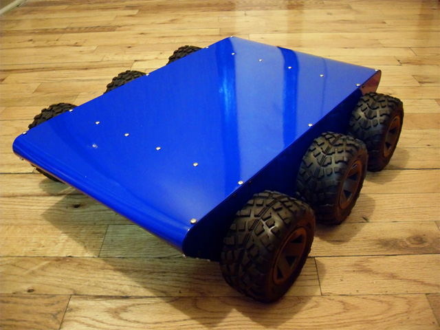
 My new 6-wheeled robot platform provides a good starting point to mount an array of sensors. Though I also plan to use this base to experiment with autonomous robotic behavior, my first plan is to add a web-cam and wireless network and be able to control the robot with my iphone! The goal with the iphone is to develop as natural as possible user interface and one very unlike traditional control interfaces.
I like the idea of controlling a mobile robot with an iphone by using the iphone's accelerometers and digital compass rather than a traditional interface using buttons. The accelerometers add a more natural control interface where movement of the robot and the panning camera is controlled by moving the iphone by changing yaw, pitch and roll. The iphone, and similar emerging devices, are changing the way we interact with the traditionally flat digital realm and instead augmenting reality --- yes, wiki Augmented Reality!
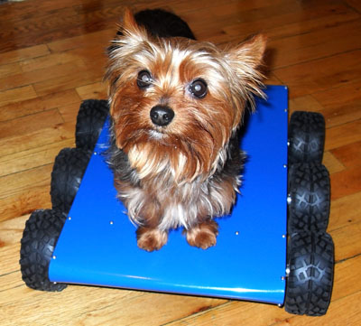
In this picture Yogi, our toy Yorkie Terrier, rides the new mobile platform. He wishes I would get to work and finish this iphone app so he can be top dog on the block!
Aluminum Frame
The frame of this robot was designed in CAD. Some of the CAD files were used to cut 1/4" aluminum stock to make the sides. More 1/4" aluminum stock were used as 5 cross bars. Sheet metal finishes it off by wrapping around the outside but the strength is given by the 1/4" aluminum built frame. This was probably over-kill. The frame could probably take my full weight standing but I could probably get away with some strong sheet metal coupled with a little reinforcement. Live and learn. I sent all the parts to the paint shop for a powder coat and the results look great!
Motor Driver Amp
I designed my own motor driver amp out of discrete MOSFETs. Designing a decent high-current motor h-bridge is a much bigger task than you can imagine. It's certainly no way to save a buck but I was in it for the learning experience. My board provide two full h-bridges and these are sequenced using a CPLD device. The CPLD provides a simple interface to the main system controller and is fully opto-isolated. The interface can be simple PWM, DIR & BRAKE signals, or with a jumper change the CPLD will enter micro-processor mode and the inputs become an interface to a simple 4-bit bus addressing internal registers for PWM duty cycle, direction and braking. The micro-processor interface really alleviates the load off the main system processor from having to provide an accurate PWM signal for variable speed control.
Power System
The entire robot's dimensions were designed with a specific battery in mind, a 15C LiPo with a whopping 8000mAh's of charge at 18.5V! This battery is 40mm x 50mm x 350mm (1.57in x 1.97in x 13.7in), this batter is long! I have enough space to add two of these batteries if I require longer running time.
Electronics
I have not integrated the main system processor board. I have a Atmel Linux board kicking around that I will probably try out first. This should provide enough computing power in the beginning. I can always buy a small SBC (Single Board Computer) later but typically more computing power will mean greater battery draw.
I also have a FPGA board that I am using now to develop a lot of the logic control. Some of the motor control logic is still being debugged. The FPGA allows me to implement Virtual Instruments that can peek into the motor controller's operation and see 100% of what is going on. This is more valuable than an oscilloscope on your desk, I can't say enough about how valuable Virtual Instruments are to developing chip logic.
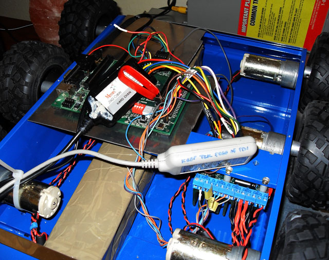
This picture shows my development setup using the FPGA board hooked up to the motor controller (CPLD) as I test and debug the motor controller's micro-processor interface. This gives me a visual interface on the computer with knobs and buttons that control the motor speed, braking and direction. I can also use this interface as a debug interface to see the state of any pin or h-bridge control output.
Network and Camera
I will tear down a small and cheap wireless network bridge router to it's basic circuit board. This will link the robot up to my home's wireless network as the Atmel Linux board I have does not already have a wireless controller. This may work out better for me in the end anyway. This Atmel Linux board could probably not handle video well nor does it have a USB port to take a cheap webcam. In this way, I can buy a network-based webcam for about 80$ and the video will stream to one of my desktop servers for processing or streaming to a web interface or iphone. A network-based webcam I have my eye on also already has the pan and tilt motor control in it. Bonus!