News
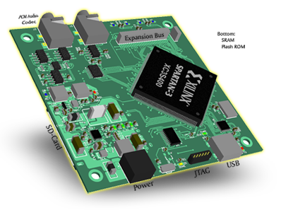
Preliminary schematics and PCB artwork are completed for an 400K gate FPGA board capable of running Linux. Features inclu de 8Mb Flash, 32MB SRAM, sound codec, SD Slot and USB. I have completed the schematics and PCB routing but I have not yet tested the design beyond some spice modeling.
The honest truth is I can't afford to take the typical 3 or more revisions to corrent any mistakes I might have in the design when each iteration costs about 600$. I have chosen to wait a little longer until my CNC machine can route decent circuits and then proceed to test the circuits seperately. This should validate at least 90% or more of the board and provide confidence it won't end up as pcb jewelery!
I have included schematics and PCB files so that you may possibly benefit from the schematics in their current state. Perhaps you may even find an error so please check my work and let me know. Finally, perhaps someone out there has the capability to cheaply create 4-layer PCBs so that together we can validate the design and share the results.
The schematics and PCB layout can be found in the PDF document at the bottom of this article.
Please, visit the polls section and vote on what you would like in a robotics main board. This board is being redesigned for this purpose.
Design Features
Mimzy currently has the following features:
- Xilinx XC3S400 FPGA & XCF02SV020C Platform Flash
- 8MB Flash ROM
- 32MB of SRAM
- PCM3008 Hi-Q Burr-Brown Stereo Audio Codec with digital volume control
- 8 Port ADC
- FTDI USB 2.0 High Speed UART
- SD Card Slot
- Bus B expansion interface
- Switching Power Supply 3.3v & 1.2v
- 2.5 or 1.8v Vaux LDO supply from 3.3v
- Negative 3.3V switching supply
- 4 user LEDs, program button and JTAG port
Notes
This design has been scaled down from more complex schematics to speed time to production. Further enhancement of the design will continue as the project matures. Here are some notes concerning current state and future plans of this project:
- User IO is not yet included in the design but will before the first production manufacture of PCBs. All unmapped FPGA and ADC pins will be brought out to a user header.
- The ADC was originally intended for self-diagnostic such as current and voltage measurement, temperature and battery levels (eventually). It remains in the schematics although all self-diagnostic circuitry was removed. It was decided that a small Atmel programmable IC will be used later for the self-diagnostic and battery charge monitor.
- The Atmel programmable IC will also be used to quickly program the FPGA via USB or load from a file on the SD Card. JTAG will always be available.
- Some minor errors in the schematic document aesthetics remain as the schematics were severely moved around and scaled down from a larger design.
- One target application of this board is for robot cores.
- 100BaseT Ethernet was originally included but it was decided Wireless 802.11 will be implemented later. Wired networking was removed because I wasn't going to waste valuable time developing two networking drivers. Considering most applications of this board will be as an embedded appliance or robotic device, why tie it down to wired networking! Wired networking is so passe!
- Host USB is also planned. Not sure if the Client side USB would remain, but probable. Host USB will really open up this board to the outside world.
- The Bus B expansion is the bus the Flash ROM is connected on and includes unused chip select lines. The expansion header allows other peripherals to be connected and memory mapped.
Download
Download the Mimzy Schematics & PCB (PDF)
 Your First CPU