Computer Numerical Control (CNC)
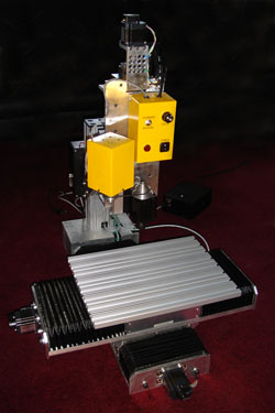
![]() My CNC Mill is finally completed after about 9 months of obsessive effort. I have already milled a few parts for a second CNC machine, a plastic doggy bone and a few PCBs have been drilled and routed. The plastic doggy bone was only 1 x 1/3 inches but the detail was fantastic!
My CNC Mill is finally completed after about 9 months of obsessive effort. I have already milled a few parts for a second CNC machine, a plastic doggy bone and a few PCBs have been drilled and routed. The plastic doggy bone was only 1 x 1/3 inches but the detail was fantastic!
The accuracy exceeds the measurability of my digital caliper (1/2mil resolution) so I am quite impressed with the results! So far, I am limiting my materials to plastic, machinable wax and Butterboard(tm) but will cut some aluminum shortly.
I have included some details on the construction with a few pictures.
Control Software
I have tried some windows control software, but most definately recommend EMC2 for motion control software. The real-time extensions make an obvious difference! Furthermore, emc2 has some really useful g-code extensions like variables, looping and conditional constructs that make g-code programming much easier and parametized parts possible. Also, join the emc2 mailing list for engaging topics of cnc.
See more pictures of my table and my progress at:
http://photos.colinmackenzie.net:81/Projects/cnc/
At Last!!! CNC Machine Finished!
| Axis Travel | X & Y: 16" x 14", Z: 8" |
|---|---|
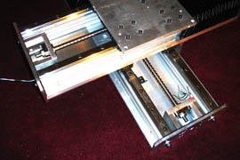
| Linear Bearings & Rails | X & Y: THK 25mm HSR w/ 24" rails, Z: NSK LWLF24 w/ 12" rails |
| Ball screws | X & Y: NSK C7 W1504-149S-C7T , Z: THK ???? |
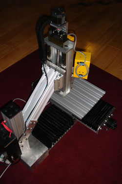
| Base construction | 80/20 Aluminum Extrusions, Standard Aluminum stock & 3 Tooling Plates used as carriages |
| Spindle / Cutting Tool | Taig ER-16 Spindle using Rick Lane's DC Motor and controller |
| Stepper Motors | Vexta 2.3ohm/3A (per phase), ?? oz-in |
| Stepper Amp/Controller | Mechatronics 4 axis - 40v 3A/phase Chopper Drive, (see autohec on ebay) |
| Power Supply | Custom Made 25v 40A Regulated DC Supply |
| Control Software | EMC2 on Ubuntu |
| Control Hardware | PC with solid-state HD or Laptop, controlled via Parallel Port |
Installing New Precision Ground Ballscrews
Oh, Boge! I have almost completed the entire assembly of this pain-painstakingly long project! Though I have no regrets making my own machine, it is a long and arduous task when using a "sledgehammer to hang a picture nail". Metaphorically, That's the best way I can think to describe my experience trying to attain 1/1000th of an inch tolerances with common *sloppy* workshop tools.
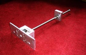
The ball-screw mounting bracket shown here securing the bearing housing of the ball-screw to the end-plate has probably been the most difficult to get right. Any slight inaccuracies in these parts could easily and drastically put my ball-screw out of alignment.
The two parts that offset the bearing mount were the most carefully constructed. If they are not precisely equal in length, or slightly angled, this small error would be large at the opposite end of the 18" ballscrew. To ensure accuracy, I rough cut the two pieces oversized, then bolted them together for all remaining operations. First I used my miter saw again to trim the sides even. I also mitered the four ends needed for clearance of the servo bolts.
I then placed in a vise to square one end with reference to the large side face. Now comes the tough work. Using my drill press and a square end mill toolbit (not recommended in a drill press), I carefully honed the end to square taking about 10mils or less off each pass until the entire surface had been milled. I turned the part around in the vise for the other end and repeated. Then, to ensure no error from the vise, I milled one end again without the vise but with the bottom end on the drill press table. Taking only about 4 mils or so in the final pass makes for an accurate and nicely polished finish. After deburring with a wire brush, the bolts are removed and the parts are seperated. It wasnt important that the length be dead accurace as the motor/screw coupler handles the difference, only that the left and right parts be exactly equal and square.
A Sledgehammer for Picture Nails
I must mention how difficult it can be to use hardware store grade tools to make parts accurate to a thousands of an inch. It's like hanging picture nails with a sledgehammer! I have a 20" compound miter saw with a metal blade the cuts aluminum like butter but hardly straight. Merely the force of my hand can throw the cut off by 1/100ths of an inch. No problem for wood projects and renovations, but not for cnc. All cuts must be checked. For improved accuracy first rough cut, then take a second cut shaving off only a minor amount. The second pass is much easier on the tool and so the cut is more accurate. Yet still, don't stop here if your part has close tolerances.
I also have a drill press. When properly balanced and the toolbit checked for runout it can drill very accurate holes. The problem is the drilling of metal holes means I am always rebalancing the machine. This means mounting my radial caliper and checking the drill chuck a lot! An unbalanced chuck and/or runout means a noisy drill, considerable power lost as heat, and an inaccurate hole. If your part is getting very hot quickly, check your tool! I also use a cutting/drilling/tapping lubricant called Butter Cut.I am learning that it's the machinist that determines the accuracy, not the tool! With good machine practices you can achieve greater accuracy...and successfully hang a picture nail with a sledgehammer. Engineering the parts with regard to what your tools are capable of is mandatory.
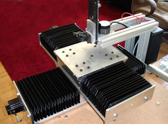
Old temporary base axii, with homemade bellow covers
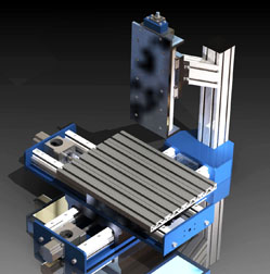
Here is the old table shown beside the ray-traced engineering model of the final design. This temporary setup allowed me to test my software suite, some of the hardware, and gain some CNC and machining knowledge before I finished my design...it helped! The machine is shown with the homemade bellow covers and the temporary Z axis. The cutting table is also removed in the picture. The cutting tool or spindle has not yet been modeled as I don't yet know which spindle I will be using. Work is well underway to complete the machine.
Cutting Table
The new cutting table is made with 1" x 3" T slotted 8020 (P#3034). The internal cutouts of this series extrusion seems ideal for making a vacuum table. I will seal the ends of the extrusions and cut small holes from the top to reach the inner cutouts. These small holes will hold the part to the table. Another hole will be cut in the bottom of each of the 8020 extrusion spars (4 of them). Tubes will route these 4 holes through the table base to the compressor. An air tank and pressure sensor and a switch will be rigged to turn on the compressor when the compression drops below a tuned value.
Z Axis Tower
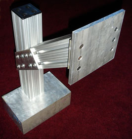
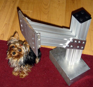
I have completed the roughing of the new Z axis tower! This tower is heavily constructed to minimize vibration and deflection! The base of the tower contains a 3" x 4" x 6" brick of heavy aluminum that helps counter the weight of the z axis that is suspended about 6" from the vertical tower span. The weight of z axis extended out so far provides quite a "moment on inertia" (or torque) on the base of the machine, I did not want that moment force to be exerted on the base assembly whose accuracy would be sensitive to deflection.(Yogi, our little yorki decided to pose for the picture!)
Z Axis Assembly
The new Z axis is assembled and is ready to be mounted to the new Z tower. The axis assembly is mounted reversed, so the carriage plate is mated to the tower, and the bulk of the Z axis moves vertically. This should provide the most use of the Z axis's travel. However, it means more force is exerted on the Z axis assembly and drive components to lift the assembly and cutting tool. In some sense, this force could be advantageous as it is directly down and on the part to be cut. In theory, less rebound cutting forces from cutting a part would directly act on the bearing surfaces and drive components as the weight of the Z axis assembly would buffer it; think "conservation of momentum" and flywheels.
Protective Bellows
The homemade bellows are made from plastic kitchen cutting sheets sandwiched with garden PVC plastic sheeting and duct tape. The kitchen cutting sheets are first cut into strips with 45 degree cuts at their ends. These are then crazy glued onto the garden plastic PVC (10mil) to form the required bellow pattern. Once dry, duct tape is applied over the glued strips and pressed into each crevice.The entire sheet is then trimmed and folded into the required shape. These bellows are certainly resistant to oil, but time will tell how they hold up against hot flying aluminum chips!



 Your First CPU