6 legged symmetrical walking robot
Symapod is a hexapod (six-legged) walking robot. Symapod is short for symmetric-hexapod. This is my second robotic walker and this one will be gra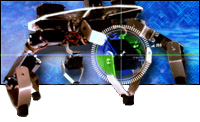 nd, I decided this time I would also build it on good looks!
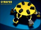
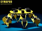
The body of Symapod: I used the circuit board as the body for weight saving and futuristic looks. The PCB appears to be quite strong but I may add a brass frame if neccessary. Symapod has its legs oriented in a star configuration. This star configuration allows it to instantaneously travel in any direction without turning or re-orientating itself. As you can see in the picture there is no front to Symapod! The head, which is not built yet, will mount in the middle on a 360-degree swivel joint.
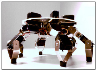
The head (which is not built yet) will mount in the middle on a 360-degree swivel joint. It will contain dual image sensors (active pixel matrix CMOS) and infrared ranging through the popular DIRRS sensors.
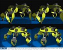
Conceptual Construction
Final Robot Design
Servo Control
I have found that although hobby servos are mechanically well suited to mini-robotic applications they aren't easy to control. For example, a complex Timer Processing Unit (TPU) would be needed to control the 18 servos present in my walker. Also, without added sensors and circuitry there is no way of k
nowing when or if a servo has reached its destination or if it hit an obstacle along the way. Also, not knowing when the leg has hit the ground makes robot walkers using standard servos to have problems when encountering rough or uneven terrain. For these reasons, I found it necessary
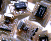
to modify the standard servo and create tiny digital servo controllers that replace the tiny circuit boards inside each standard servo. This little replacement circuit board turns any standard servo (which uses Pulse Code Modulation) into a digitally controlled servo using the standard and easily implimented I2C bus, a simple multi-client serial type protocol where all servos share the same 2-wire bus. This protocol takes a large processing load off the robot's master controller (brain). The robot can also read or write the current position, force feedback and speed of each servo. There were a total of 18 of these controllers made for my robot, one to match each servo. You can see pictures of these tiny servo controllers on my web site.
Construction
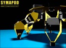
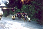
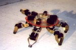
The base of the robot is the Printed Circuit Board (PCB) itself. The PCB contains Symapod's sensors and master controller (brain). Symapod was designed for travel over uneven and rough terrain with each leg boasting 3 DOF making a total of 18 R/C servos each modified with a custom digital servo controller. The PCB appears to be quite strong without further reinforcement. The legs are made of the servo's themselves coupled together with bent brass strips found from any local hobby shop. Mechanically, it's a simple design that remains strong and easy to work with. I will look at further cosmetic shell enhancements once the mandatory design work is complete. I have also tried to keep as few wires showing as possible.


 Your First CPU